LumiSnap

THE LUMISNAP FIELD GUIDE / ABOUT 30 MINUTES

A practical guide
to HDR measurement

Learn camera setup, exposure bracketing, luminance calibration and methods for daylight and glare studies, then use the images to answer design questions. A practical introduction for architecture students.

LumiSnap is used to teach lighting and daylighting in architecture at Cornell University and MIT.

Jump to the field checklist ↓
A real fisheye exposure from the supplied lecture-hall capture series
Example fisheye exposure from the supplied capture series.

01 / FIRST PRINCIPLES

Luminance and illuminance

Think of a window lighting a desk. Illuminance describes how much light arrives at the desk. Luminance describes how bright the desk, the wall or the window is in a particular direction. A calibrated photograph maps luminance across the view.

cd/m²

Luminance

Light travelling from a surface or source toward the camera. A spot luminance meter measures one small part of the view; a calibrated HDR records many directions at once.

lx

Illuminance

Light arriving on a plane. A lux meter on a desk faces up. At the eye position it faces forward. The position and orientation are part of the measurement.

High dynamic range imaging

A camera sensor has a limited usable range: weak signals disappear into noise, while strong signals saturate, or clip. One photograph may preserve the room but lose the window, or preserve the window but lose the room. A bracket records the same scene at several exposure times. The merge combines the useful parts into a high dynamic range (HDR) image.

A linear HDR preserves ratios: twice the value represents twice the light signal. Calibration gives that signal a physical scale. A screen preview compresses the range to make it visible; a false-colour view assigns colours to numbers. Neither a pleasing preview nor a phone’s ordinary “HDR photo” proves that the data are calibrated. Keep the numerical Radiance HDR as well as any presentation images. [1]

02 / STUDY AND VIEW SELECTION

View selection for daylight and glare studies

Daylight & model studies

Compare light distribution on ceilings, walls and work surfaces, or test a shading or rooflight design. A normal lens can document a selected area. Keep the camera view and false-colour legend consistent between alternatives.

In a physical model, put the lens at the equivalent occupant position. Keep materials, glazing, model scale and sky conditions documented, and avoid blocking openings with the camera. Lux readings on a workplane answer a different question from surface luminances in the image.

Glare from an occupant’s view

The LumiSnap glare workflow requires a fisheye lens and a complete 180° hemispheric view. Put the lens at the observer’s eye position and aim along the intended gaze direction. A narrow image omits light sources and changes their apparent sizes and positions.

A standard iPhone ultra-wide lens is not a 180° fisheye. Phone captures remain useful for luminance studies; use a characterized fisheye setup for the desktop glare workflow. An add-on lens also needs its projection, field of view and vignetting checked.

For a daylight study, DGP (Daylight Glare Probability) helps assess discomfort from the captured view. UGR (Unified Glare Rating) is primarily an electric-lighting metric. Interpret each within its intended application; a single view at one time does not describe a room’s annual daylight performance. Section 07 pairs each design question with its metric.

A separately calibrated sky capture can also provide lighting input to a daylight simulation. That is a different capture from an interior view: it needs the sky hemisphere, orientation and a treatment of the sun. An interior photograph alone is not an annual sky model. [5]

03 / THE FIELD SETUP

Camera setup and positioning

Bring a tripod, a remote release or timer, a matte neutral target, and a calibrated spot luminance meter. A separate illuminance meter is strongly recommended for validation. For glare, add a fisheye that covers the full forward hemisphere on your camera’s sensor.
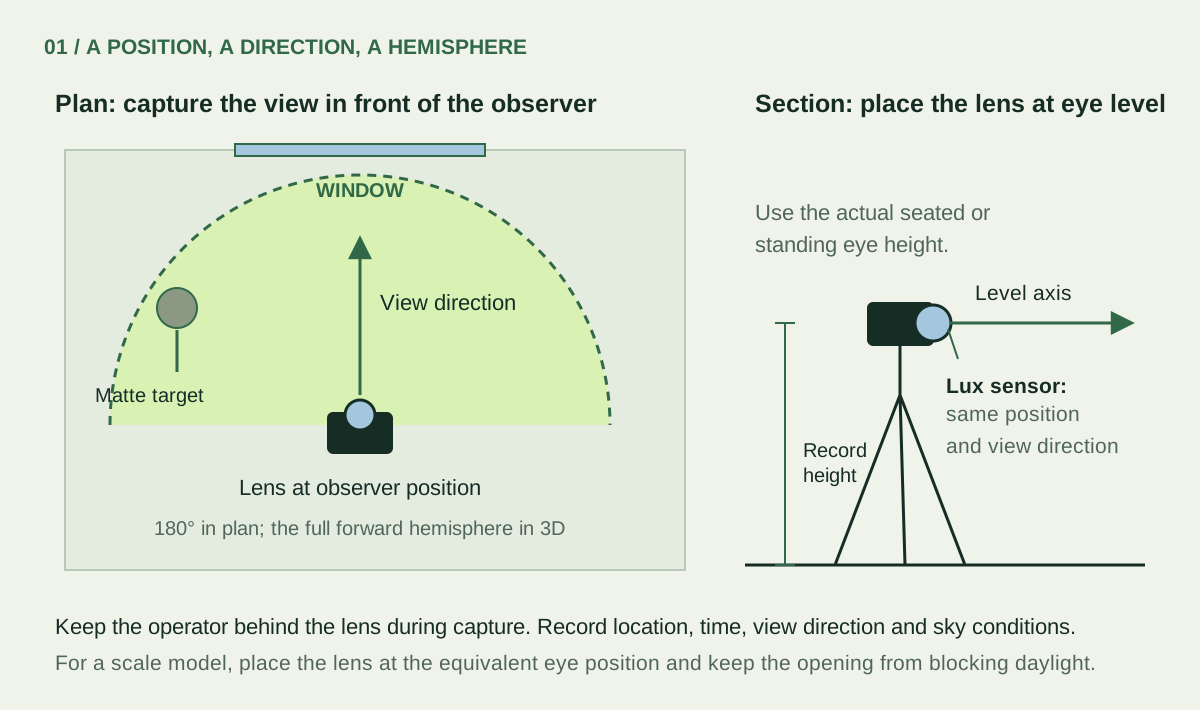
Plan and section of a fisheye camera at the observer position, with the lens at eye height and a lux sensor facing the view direction
Record the observer position and gaze direction. On small screens, scroll the diagram to inspect labels. Download editable SVG ↓
Camera controls: what to fix, and why
ControlPractical starting pointWhy it matters
Shutter timeChange it for each exposure.A longer exposure collects more light without changing lens geometry.
Aperture / f-numberFix it for the whole bracket. For an interchangeable-lens camera, f/8 is a starting point to test, not a universal optimum.Aperture affects depth of field, vignetting and flare. Use corrections measured at the aperture you actually choose.
ISOUse a fixed, low native ISO, often 100, when the setup permits.ISO changes signal gain; it does not collect more photons. More gain can reduce highlight headroom.
Focus & white balanceFocus once and lock it. Use a fixed white balance.Refocusing and changing colour processing make exposures harder to combine consistently.
Image processingFor JPEGs, use consistent settings; disable automatic contrast, HDR, local tone changes and automatic lens corrections.A global response curve cannot undo changing local edits. Keep JPEG picture settings tied to their response calibration.

RAW stores sensor data before much of the camera’s picture processing. Bayer sensors sample red, green and blue through a filter mosaic; software reconstructs a colour image. RAW still needs correct black-level, exposure and colour handling, followed by physical validation. JPEG has already been processed and compressed, so its nonlinear brightness response must be accounted for. [1]

On iPhone: LumiSnap manages adaptive Bayer RAW brackets on supported devices and lenses. Most phone lenses have a fixed aperture. Stabilize the phone, keep one supported lens, and inspect the saved coverage view after capture. Export the completed session ZIP to desktop with its saved HDR and measurements. Desktop merges camera JPEG brackets; it does not develop arbitrary camera RAW files.

04 / THE CAPTURE STRATEGY

Exposure bracketing and range coverage

One exposure stop (1 EV) doubles or halves the collected light. At fixed aperture and ISO, 1/30 s collects about twice as much as 1/60 s. Start with overlapping exposures roughly 1–2 stops apart, then extend the range to suit the scene. The number of frames is a consequence of coverage, not a target.
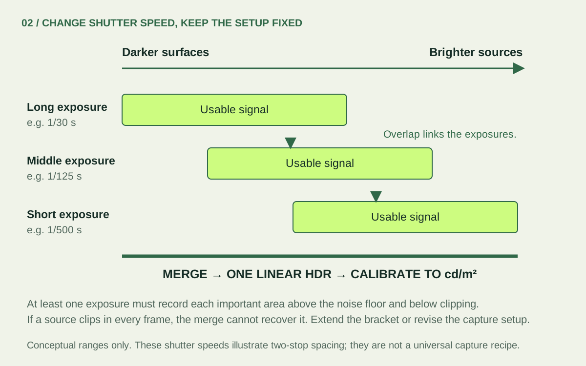
Overlapping useful ranges from long, medium and short exposures combine into a linear HDR; sources clipped in every exposure cannot be recovered
Overlap connects the bracket. The range bars are conceptual, not measurements from the example. Download editable SVG ↓
  1. Check the short exposure. Important bright sources must remain below clipping in every colour channel in at least one frame. Inspect source pixels and coverage, not just the overall histogram.
  2. Check the long exposure. Dark surfaces you intend to measure need usable signal above noise. Keep enough intermediate frames to overlap.
  3. Watch the scene. Clouds, moving blinds, flickering lights and people can break the assumption that only the exposure changed. Capture promptly and repeat if conditions change.

Explore the supplied fisheye bracket

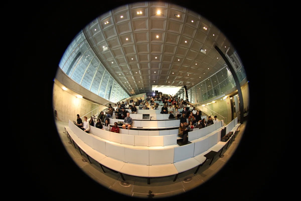
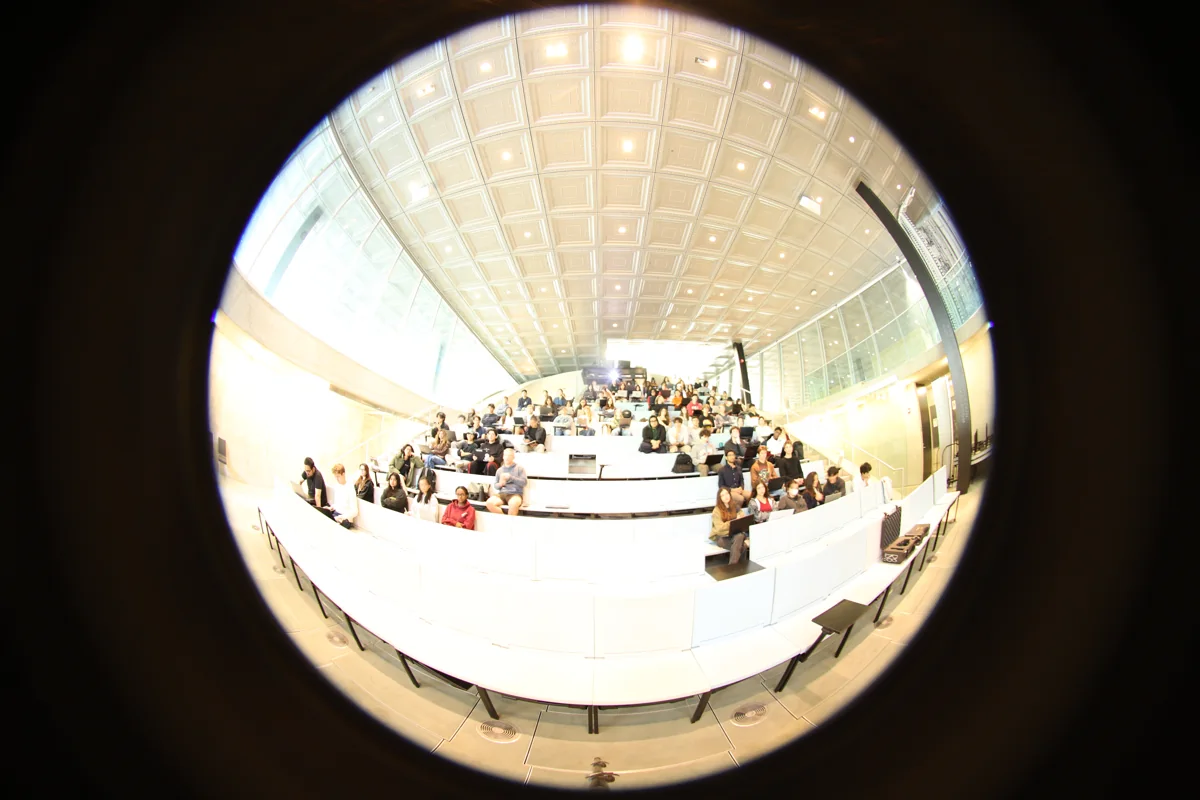
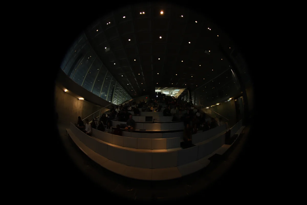
These are real JPEGs from the project’s example series: Canon EOS 6D Mark II, 8 mm lens, f/4, ISO 200. The 11 frames run from 1.3 s to 1/50 s: about six stops between the endpoints, with uneven spacing. They span about a minute. This is an example to inspect, not a recommended bracket length or a certified measurement.

Long exposure: front desks are bright and some highlight detail is lost
1.3 s / room detail
Middle exposure with darker desks and ceiling
1/4 s / intermediate overlap
Short exposure preserving more detail near the bright ceiling lights
1/50 s / highlight check

HDR cannot repair missing measurements. A source clipped in every exposure remains unknown. Direct sun and strong reflections can exceed an ordinary bracket’s range; they can also create flare that spreads light across the image. A characterized neutral-density filter can help capture brighter sources, but changes transmission and colour and needs its own correction. A darker-looking preview does not demonstrate that the sun is measured. [2] [3]

05 / MEASURE WHILE YOU CAPTURE

Reference measurements for calibration

Select a luminance or illuminance meter

White diffuser: place it where you want to measure arriving light. The Konica Minolta T-10A is an illuminance meter and reads lux (lx). Lens and viewfinder: aim at the surface you want to measure. The LS-150 is a spot luminance meter and reads cd/m². Its central 1° measuring circle selects a small patch; the larger viewfinder helps you aim.
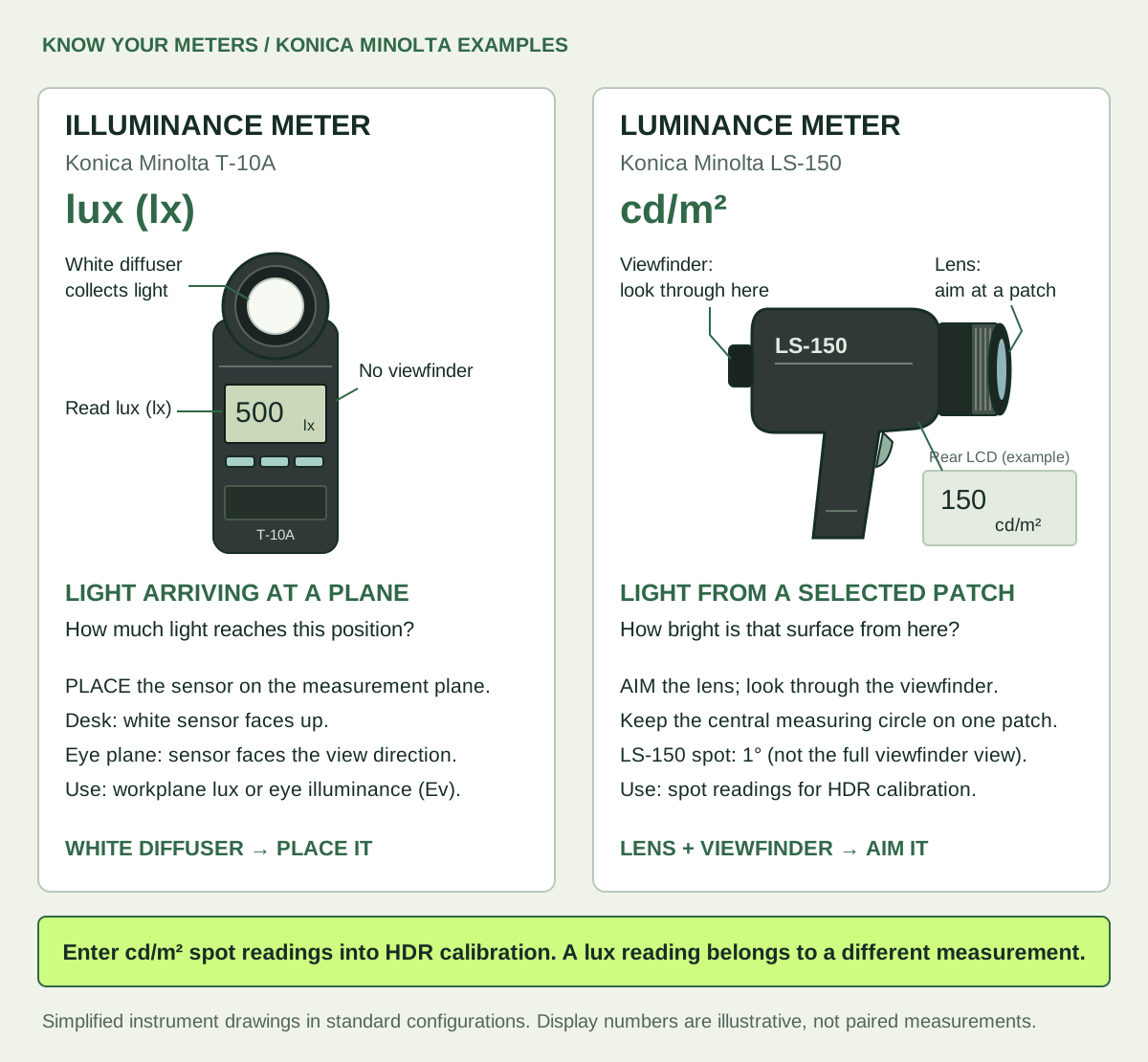
Konica Minolta T-10A with a white diffuser: place the sensor on a plane to measure illuminance in lux. LS-150 with a lens and viewfinder: aim at a selected patch to measure luminance in cd/m² for HDR calibration.
Recognize the sensor, check the unit, then choose how to position it. Simplified drawings of standard configurations; example display readings are not a conversion between lux and cd/m². Manufacturer references: T-10A · LS-150. Download editable SVG ↓
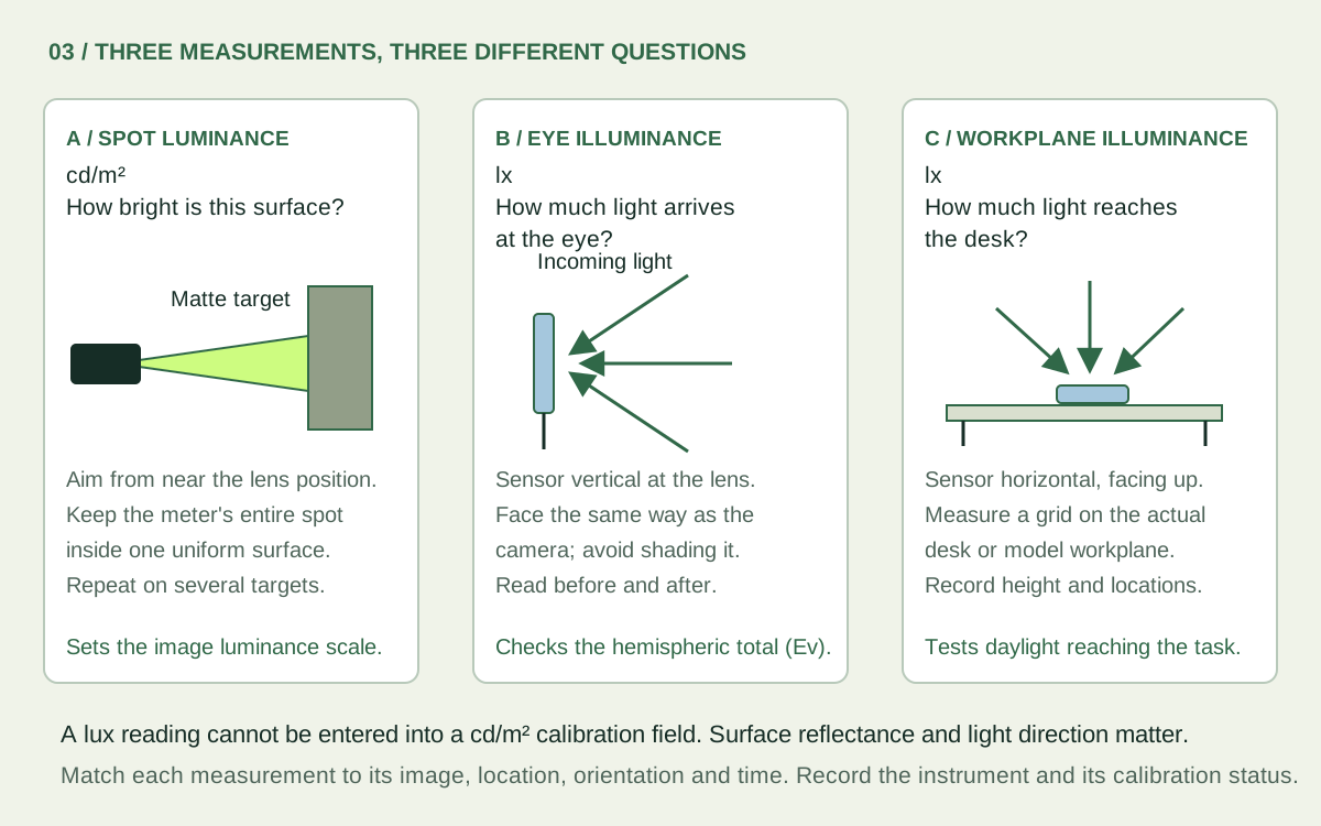
Compare a spot luminance meter aimed at a matte target, a vertical lux sensor at the eye, and an upward-facing lux sensor on a desk
The unit, position and sensor orientation tell you what a reading means. Download editable SVG ↓

A / Spot luminance: set the image scale

Measure several matte, evenly lit patches visible in the image, covering darker and brighter surfaces. Aim from near the camera position and record exactly which patch you measured. Avoid glossy surfaces, edges, shadows and clipped areas. A grey card is convenient, but “18% grey” does not specify its luminance: you still need the meter reading.

The target must fill the meter’s acceptance cone. For example, a 1° spot is about 5.2 cm across at 3 m, so use a larger uniform patch. In desktop, choose the matching meter angle; on iPhone, choose an image sampling region contained in the same uniform patch. Take repeat readings and reserve at least one target as an independent check.
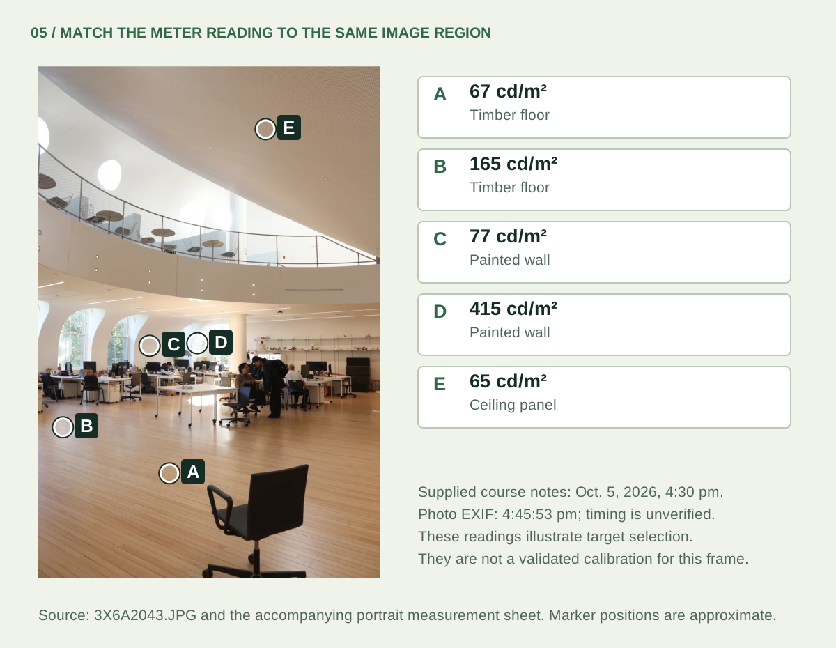
The supplied portrait photo with five approximate target positions and recorded readings: A 67, B 165, C 77, D 415 and E 65 cd/m²
Actual supplied portrait capture and course readings, redrawn with editable annotations. The notes say 4:30 pm and the frame’s EXIF says 4:45:53 pm; use this to learn target selection, not as a verified simultaneous calibration. Download editable SVG ↓

B / Vertical illuminance: check the whole view

Place a cosine-corrected lux sensor at the lens position, vertical and facing along the camera axis for a level view. Measure before and after the bracket without shading it. This records Ev, the illuminance arriving on the eye plane. Compare it with illuminance integrated from the corrected hemispheric HDR. A narrow view misses part of that total. Before/after readings also reveal changing daylight; if conditions change appreciably, repeat the sequence. [2]

C / Workplane illuminance: test the design

For a desk or physical daylight model, place the lux sensor horizontally, facing up, on a documented grid at the intended workplane. This measures light reaching the task. It does not replace a spot luminance reference or a vertical eye-plane reading. There is no universal lux-to-cd/m² conversion: even the ideal diffuse-surface relationship depends on reflectance.

What needs measuring once per setup, and once per capture?

Characterize the camera and lens: JPEG response, usable luminous range, projection, field of view, image circle and vignetting. Vignetting is the lens’s gradual darkening toward the edge. Under stable controlled lighting, a lab can track the same target at different off-axis positions by rotating the camera about the lens’s entrance pupil; the measured fall-off gives a correction for that lens and aperture. Recheck after changing relevant settings, filters or equipment.

For each scene: record the spot readings, before/after Ev, timestamps and view, together with clipping and movement checks. Workplane readings are additional evidence for a daylight study. A global scale factor cannot correct spatially varying lens fall-off, flare or missing highlights. [1] [2] [4]

06 / IMAGE PROCESSING AND VALIDATION
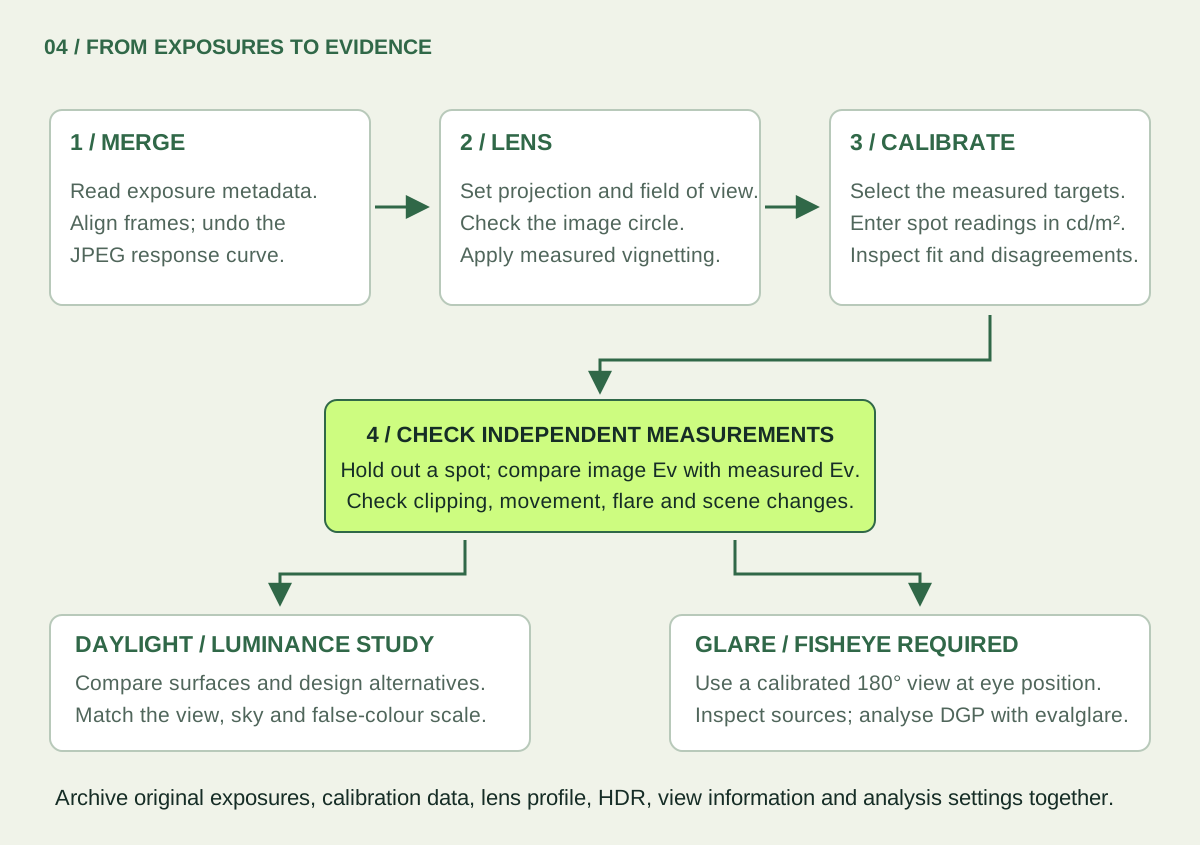
HDR calibration and validation

Merge exposures, correct lens geometry and vignetting, calibrate using spot readings, independently validate, then analyse daylight or fisheye glare
The desktop workflow, with checks before interpretation. Download editable SVG ↓
  1. Merge and inspect. Import JPEG brackets with correct exposure metadata, or open a completed iPhone session. Check alignment, coverage and bright-source detail. Do not merge tone-mapped screenshots.
  2. Prepare the lens. For a fisheye, confirm the image circle, true field of view and projection. Apply the relevant vignetting correction: LumiSnap Desktop identifies the lens from EXIF and takes its profile from the Lensfun database, installed Adobe lens profiles or a profile you measured and saved yourself. Published profiles were measured on other bodies; your own measurement is more accurate. LumiSnap can resample to the angular fisheye used by Radiance and evalglare; the camera’s own fisheye projection may differ.
  3. Add spot readings. Select the same patches in the HDR and enter cd/m². A simple example: a target that reads 120 in the unscaled image and 150 cd/m² on the meter implies a scale factor of 150 ÷ 120 = 1.25. LumiSnap combines multiple valid points and shows their deviations.
  4. Validate separately. Compare a held-out target and the measured Ev with the image. A target used to fit the scale is not an independent validation. Report disagreements; do not keep rescaling until every check appears to pass. [4]
When a check disagrees, look for a cause
ObservationWhat to investigate
One spot is far from the othersWrong target, aiming error, glossy material, too-small patch, shadow, movement or changed light.
Errors grow near the image edgeVignetting, an incorrect projection, field of view or image circle.
Spot checks agree but image Ev is lowMissing/clipped sources, cropped hemisphere, lens correction, sensor orientation or a time mismatch.
Bright halos or duplicate peopleLens flare or motion between exposures. Alignment cannot turn a changing scene into a static measurement.

For glare: use the calibrated full fisheye at the intended viewpoint, inspect the source-detection image, and compare with evalglare on desktop. Source luminance, angular size, position and eye illuminance all matter. Any replacement of clipped source values is an estimate; preserve its method and measured inputs in the report. [3]

For a design comparison: retain common units and colour limits, matched views, sky conditions and light settings. Save the original bracket, measurement log, lens corrections, calibrated HDR and processing settings. Report the moment and viewpoint the image represents; a false-colour PNG is useful communication, but does not retain the full HDR data.

07 / USE IT IN DESIGN

Seven design questions an HDR can answer

A calibrated HDR is not a diagnostic picture of a finished room. It is a way to calibrate your intuition and to test design moves. Start from the design question. Change one design variable, capture again from the same position, and compare the metric that answers the question.

Questions, design variables and metrics
QuestionDesign variablesMetricCapture
1 / Will this be uncomfortable?Window position, shading, desk orientation, glazing transmittanceDGP, UGR; source luminance and solid angle180° fisheye at the eye
2 / Bright or gloomy?Wall and ceiling reflectance; where light landsMean luminance in the 40° horizontal bandLevel fisheye or wide view
3 / Calm or dramatic?Aperture size and distribution, depth, material contrastLuminance ratios, spatial contrast, histogram spreadFixed view
4 / How does it change?Orientation, seasonal sun penetration, atmosphereBand mean and contrast over time; hours above a glare thresholdTime-lapse, fixed camera
5 / What is this material doing?Finish selection; inputs for digital modelsρ ≈ πL / ESample with a lux reading or a grey card
6 / Does my model tell the truth?Trust in physical models and simulationPer-region log ratio; histogram comparisonSame view in model, space and rendering
7 / What does the eye receive?Daylight access at the occupant’s positionEv from the image; melanopic estimate180° fisheye at the eye

1 / “Will this be uncomfortable?” Glare

Design variables
Window position, shading, desk orientation, glazing transmittance.
Metric
DGP and UGR from evalglare on a calibrated 180° fisheye at eye position. Also report each glare source’s luminance Ls and solid angle ωs, and the threshold that defined it: a fixed 2,000 cd/m², or 5× the task-zone mean luminance.
Read it as
DGP below 0.35 imperceptible, 0.35–0.40 perceptible, 0.40–0.45 disturbing, 0.45 and above intolerable. UGR is primarily for electric lighting; 19 is a common limit for offices.

DGP = 5.87·10⁻⁵ Ev + 9.18·10⁻² log₁₀(1 + Σ Ls² ωs / (Ev1.87 Ps²)) + 0.16UGR = 8 log₁₀(0.25 / Lb · Σ Ls² ωs / Ps²)Ev: vertical eye illuminance (lx). Ls, ωs: source luminance (cd/m²) and solid angle (sr). P: Guth position index, larger away from the line of sight. Lb: background luminance. [6]
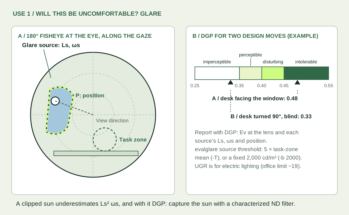
A 180° fisheye at eye position with a window glare source, the sun, its position and the task zone, and a DGP scale comparing a desk facing the window at 0.48 with a desk turned 90° behind a blind at 0.33
The source term grows with Ls², so a clipped sun underestimates DGP. Example values. Download editable SVG ↓

Compare design moves at the same desk, at the same time, from the same position. A sun-path or shading-mask study tells you when the sun can be in the view; the HDR tells you how uncomfortable it is.
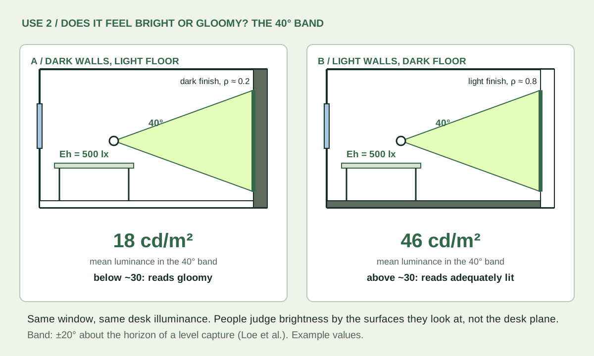
2 / “Does it feel bright or gloomy?” Perceived brightness

Design variables
Wall and ceiling reflectance; where light lands rather than how much arrives on the desk.
Metric
Mean luminance in a 40° horizontal band centred on eye level. Roughly 30 cd/m² separates spaces judged adequately lit from those judged gloomy. [7]
Read it as
Horizontal illuminance misleads. A room can meet 500 lx on the desk and still feel dim, because people judge brightness from the walls they look at.
Two room sections with the same 500 lx on the desk: with dark walls the 40° band averages 18 cd/m² and reads gloomy; with light walls it averages 46 cd/m² and reads adequately lit
Same window, same desk illuminance, different impression. Example values. Download editable SVG ↓

Mask the band in a level fisheye (±20° above and below the horizon) and average the luminance of its pixels. Repeat after changing a finish, or after moving a window so it washes a wall. A lux grid on the workplane never sees this difference.

3 / “Is it calm or dramatic?” Contrast and variability

Design variables
Aperture size and distribution, room depth, material contrast, and the intent of the space.
Metric
Task : surround and surround : periphery luminance ratios, against the IES ballpark of 1 : 3 : 10 [8]; spatial contrast [9]; and the spread of the log-luminance histogram.
Read it as
Neither calm nor dramatic is right in itself. A studio needs even light on the work; a chapel or a stair can use sharp contrast. The metric shows whether the design delivers its intent.

C = L̄ task / L̄ surroundσ = std(log₁₀ L) over the view’s pixelsA ratio of about 3 or less between task and surround, about 10 or less to the periphery. σ = 0.3 means a factor of about 2 either side of the typical value.
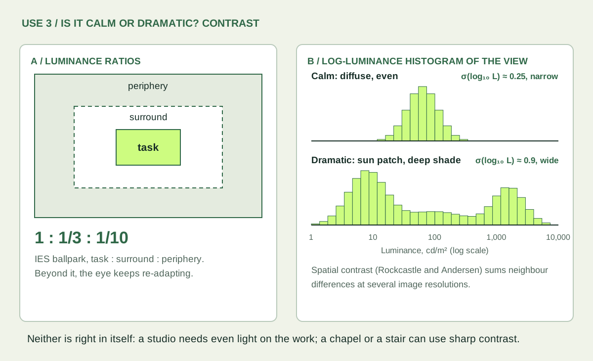
Task, surround and periphery zones with the ratio 1 : 1/3 : 1/10, and two log-luminance histograms: narrow for a calm view and wide with two peaks for a dramatic view
Spatial contrast sums luminance differences between neighbouring pixels at several image resolutions. Example histograms. Download editable SVG ↓

4 / “How does it change over time?” Dynamics

Design variables
Orientation, seasonal sun penetration, the atmosphere of the space through the day.
Metric
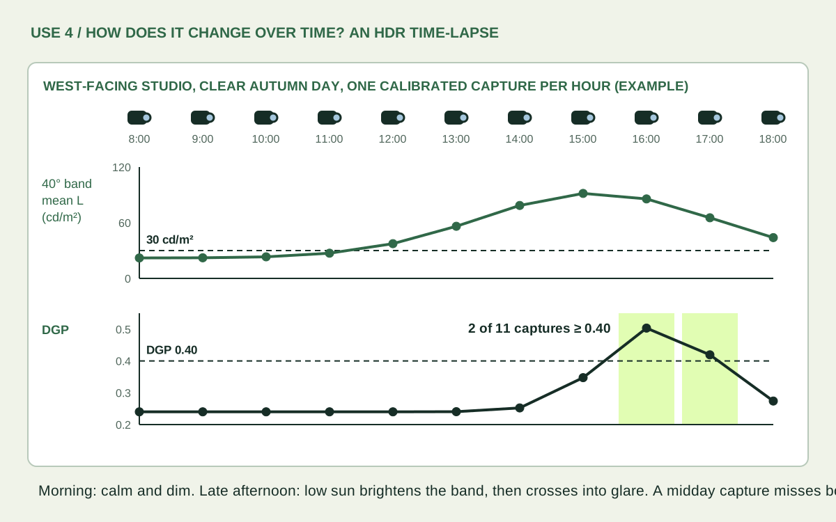
An HDR time-lapse from a fixed camera (LumiSnap for iPhone: Automation → Time-lapse): the 40° band mean and the contrast for each capture, and the number of captures, or hours, above a glare threshold.
Read it as
Treat each capture as standing for its interval. EN 17037 states glare protection as a DGP not exceeded for more than 5% of the occupied time: 0.45, 0.40 or 0.35 for its three levels. [10]
Hourly captures from 8:00 to 18:00 in a west-facing studio: the 40° band mean rises above 30 cd/m² in the afternoon and DGP exceeds 0.40 in two late-afternoon captures
A single midday capture would miss both the calm morning and the late-afternoon glare. Example values. Download editable SVG ↓

Daylight changes between captures, so record a spot reading and Ev each time, or keep a fixed reference target in the frame. One day is a sample, not a year: choose dates from the sun path, or extend the study with simulation (question 6).

5 / “What is this material actually doing?” Reflectance

Design variables
Finish selection; reflectances for digital models instead of guessed values.
Metric
Reflectance of a matte sample from its luminance and the illuminance on it, or against a grey card of known reflectance in the same light.
Read it as
Valid only for diffuse (matte) surfaces. A glossy or strongly textured finish looks different from every angle; photograph it from the occupants’ viewpoint instead of reducing it to one number.

ρ ≈ π L / Eρx ≈ ρcard · Lx / LcardL in cd/m² from the calibrated HDR; E in lx, with the sensor in the plane of the sample. With a grey card in the same light, no lux meter is needed.
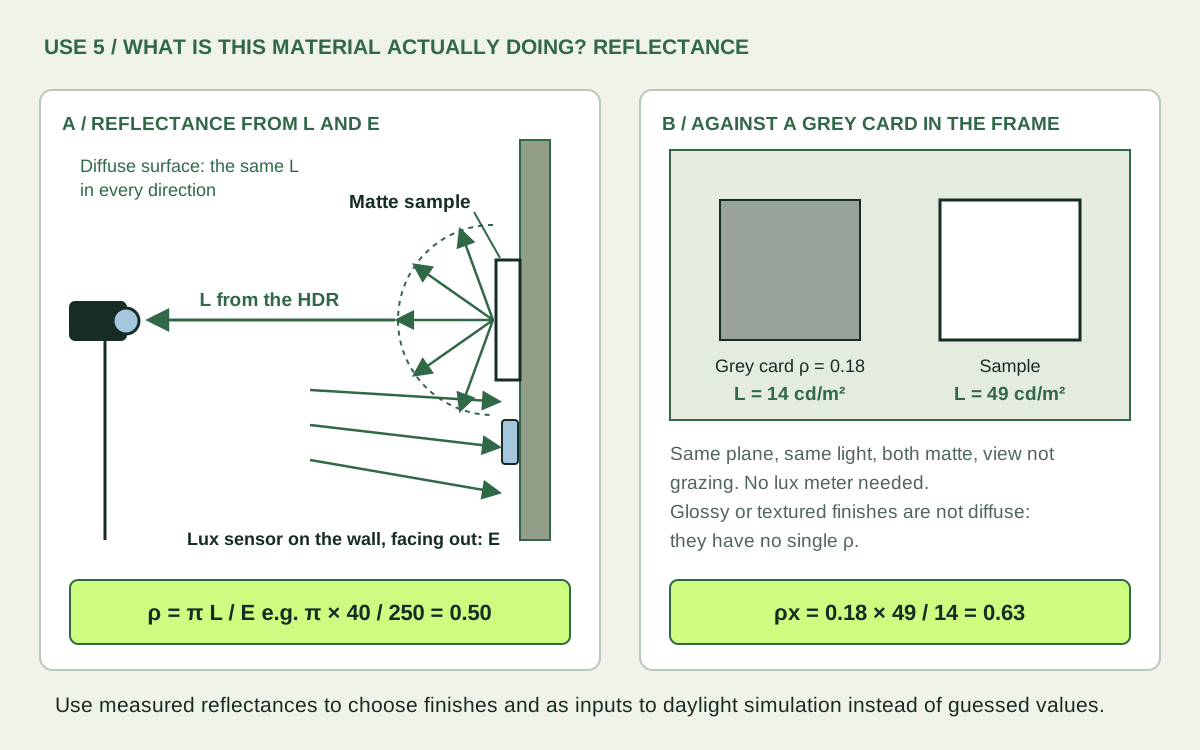
A matte sample reflects the same luminance in every direction: ρ = π × 40 / 250 = 0.50. Against an 18% grey card in the same light: 0.18 × 49 / 14 = 0.63
Two ways to measure a finish. Example values. Download editable SVG ↓

6 / “Does my model or simulation tell the truth?” Validation

Design variables
Your trust in the tools: a physical scale model, a Radiance rendering, and when to believe each.
Metric
For the same view in the real space, the model and the rendering: the log ratio of the mean luminance in each region (ceiling, walls, floor, window), and a comparison of their log-luminance histograms.
Read it as
Scale models show light leaks, material mismatches and sky problems. Finding them is the lesson, not a failure: each mismatch tells you which part of the model to fix before you use it to decide.

r = log₁₀(L̄ model / L̄ real)r = 0 agrees; ±0.1 ≈ ±26%; +0.3 ≈ twice as bright. Log ratios work across the decades a daylit view spans; a 50 cd/m² error means something different on a ceiling than on a window.
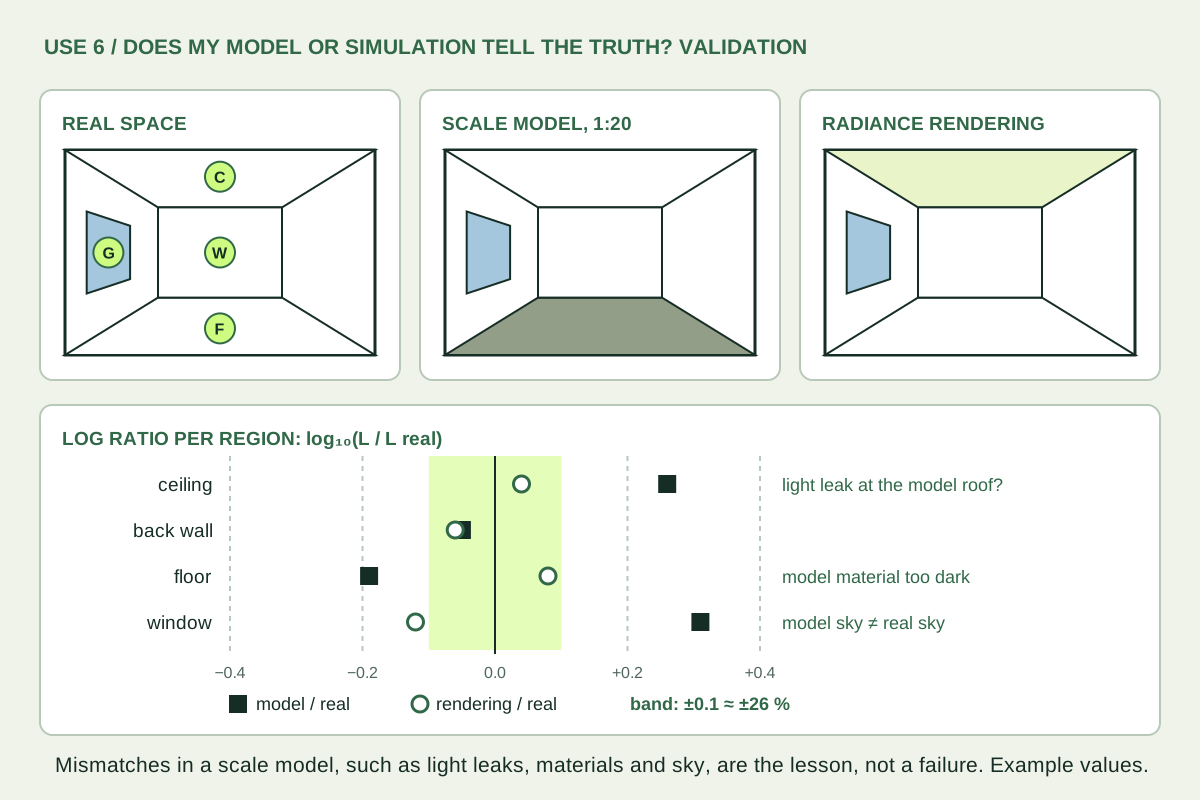
The same view of a real space, a 1:20 scale model and a Radiance rendering, with a dot plot of log luminance ratios per region: the model is too bright at the ceiling and window and too dark at the floor; the rendering stays within ±0.1
Render with the same view type (an angular fisheye, -vta, for a fisheye capture), measured reflectances and a sky that matches the capture. Example values. Download editable SVG ↓

7 / “What does the eye receive?” Vertical illuminance

Metric
Ev integrated from the calibrated fisheye. A melanopic estimate is possible if you assume a spectrum; flag it as an approximation.
Read it as
Ev drives DGP and the non-visual effects of light. It is also the check on the whole capture: compare it with the lux sensor at the lens (section 05).

Ev = Σ Li · cos θi · ωim-EDI ≈ Ev · M-DER (assumed spectrum)θ: angle from the view direction; ω: the pixel’s solid angle. An RGB camera does not measure the spectrum: state the assumed source, or use a spectrometer. [11]
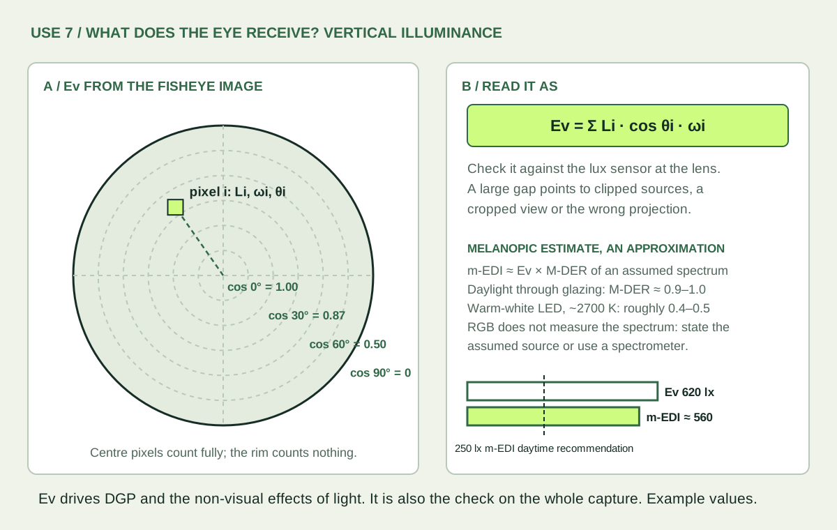
Each fisheye pixel contributes its luminance times the cosine of its angle from the view direction times its solid angle; a melanopic estimate multiplies Ev by the M-DER of an assumed spectrum, compared with a 250 lx daytime recommendation
Centre pixels count fully; the rim counts nothing. Example values. Download editable SVG ↓

Capture pitfalls to drill early.

  • The sun needs an ND filter. Without one, the sun clips in every frame and DGP is underestimated. The filter needs its own transmission correction.
  • Correct vignetting. Fisheye fall-off darkens the periphery, exactly where windows and glare sources often sit.
  • Fisheye at eye height for metrics. Glare, the 40° band and Ev need the full hemisphere from the occupant’s eye. Use perspective views for composition only.
  • Fix the camera for A/B tests. Same position, height, direction, lens and settings. Moving the camera changes the metric more than many design moves do.

IPHONE / CAPTURE TO DESKTOP

iPhone capture and analysis workflow

These two sessions were captured with LumiSnap on iPhone using the Ultra Wide lens. Each includes its original Bayer RAW exposures, a merged HDR image and saved luminance reference points. Use them to follow the workflow from capture to desktop analysis.

  1. Capture an exposure bracket. In Capture, select a lens that supports Bayer RAW. Keep the phone fixed and the scene static; a tripod is preferable. Automatic capture adjusts the bracket to cover the scene. Wait until capture and processing finish before moving the phone. Align frames and Reduce ghosts (camera settings, both on by default) correct small camera movement and use a single exposure where moving people or objects disagree; they do not replace a steady camera. For a study over time, open the sliders button → Automation → Time-lapse and choose the number of sessions, the interval and an optional start time. Keep the phone in place and LumiSnap open for the whole run.
  2. Review the merged session. Open Sessions. The HDR merges automatically. Inspect HDR, Coverage and individual Frames for clipping, dark areas, alignment errors or movement before using the image for measurement.
  3. Enter reference readings. In Calibration, tap uniform patches in the image and enter the corresponding spot-meter readings in cd/m². Match each image region to the measured patch, review the sampling radius, then tap Apply calibration. Points save automatically. Review residuals and check a separate target that was not used in the fit.
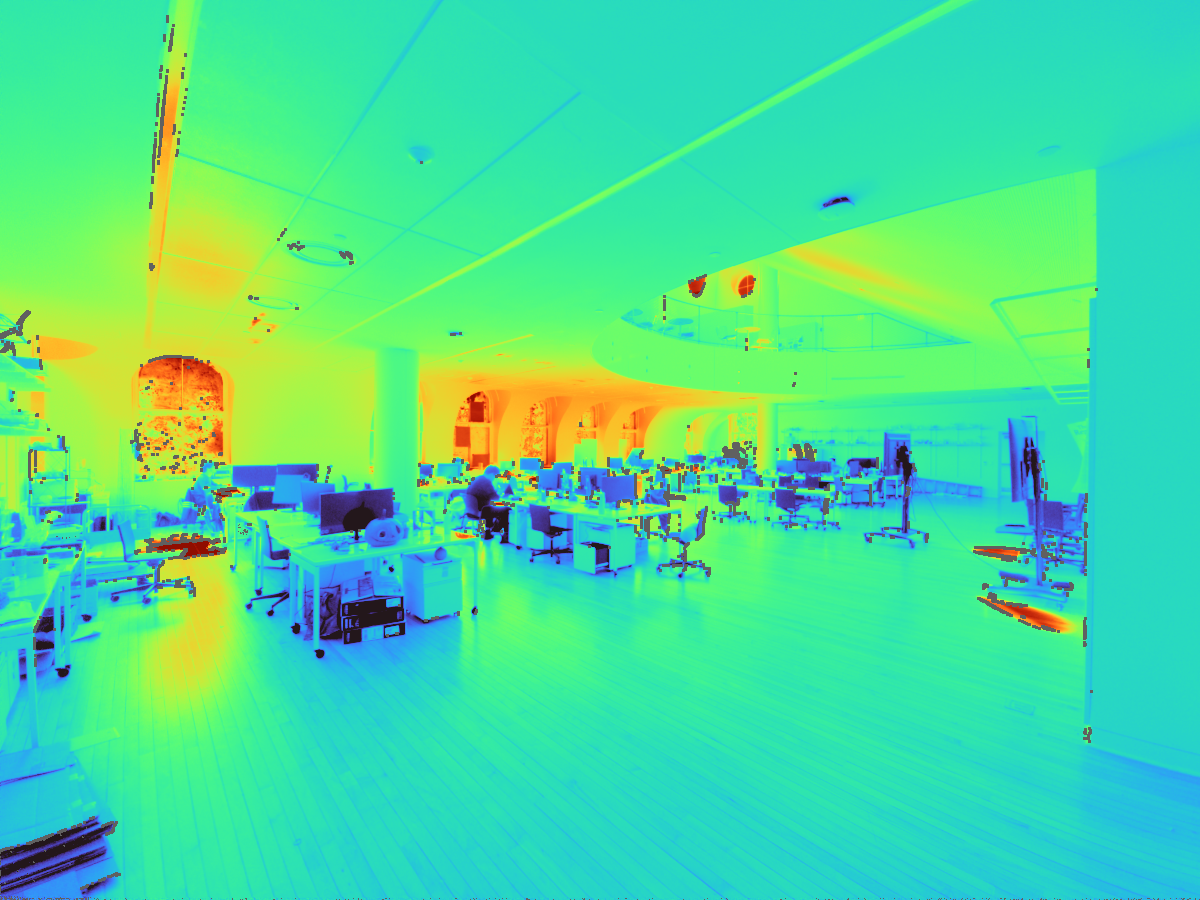
  4. Inspect luminance. Open False colour. Tap the image for a luminance readout; set the minimum, maximum and logarithmic or linear display range, and choose a colour ramp (Turbo, Inferno, Magma or Viridis). The luminance histogram below the image shows how the view is distributed; dashed lines mark the display range. Grey pixels are excluded from measurement. Display settings change the view, not the HDR values. The share button exports the view with its legend as a full-resolution PNG.
  5. Export or continue on desktop. Use the up-arrow in Sessions to export a calibrated HDR or a bracket-series ZIP. The ZIP preserves RAW originals, the saved working HDR and calibration data. In LumiSnap Desktop, choose Open project… and select the ZIP, or extract it and open session.lumisnap.json. The saved HDR opens without redeveloping the DNGs.
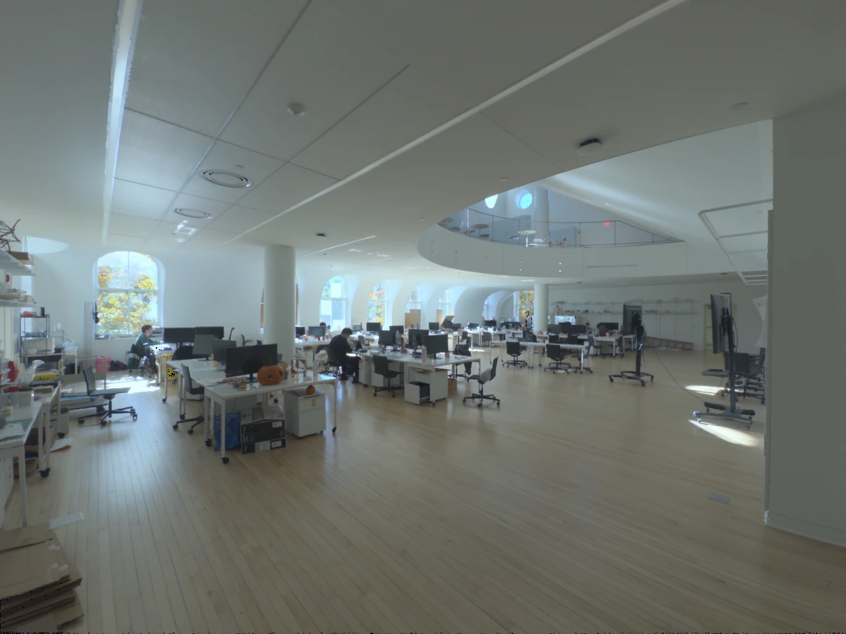
Design Tech Space

5 RAW exposures · Landscape · 4 reference points

Landscape iPhone HDR preview of an architecture workspace with arched windows, desks and a mezzanine
Tone-mapped HDR preview. Numbers mark the saved reference points.
Luminance map and reference readings
Calibrated false-colour luminance map of Design Tech Space, showing brighter windows and lower luminance across the interior
Rendered from the working HDR with its saved calibration factor, 1.0267.
Turbo colour scale from low luminance in purple to high luminance in red
101001,00010,000

cd/m² · Logarithmic scale

Saved calibration readings
PointMeter (cd/m²)Fit residual
1111.01+2.7%
2161+2.2%
3131.5−7.7%
483.5+3.1%

The saved merge excludes 1.2% of pixels from measurement. These appear grey in the luminance map.
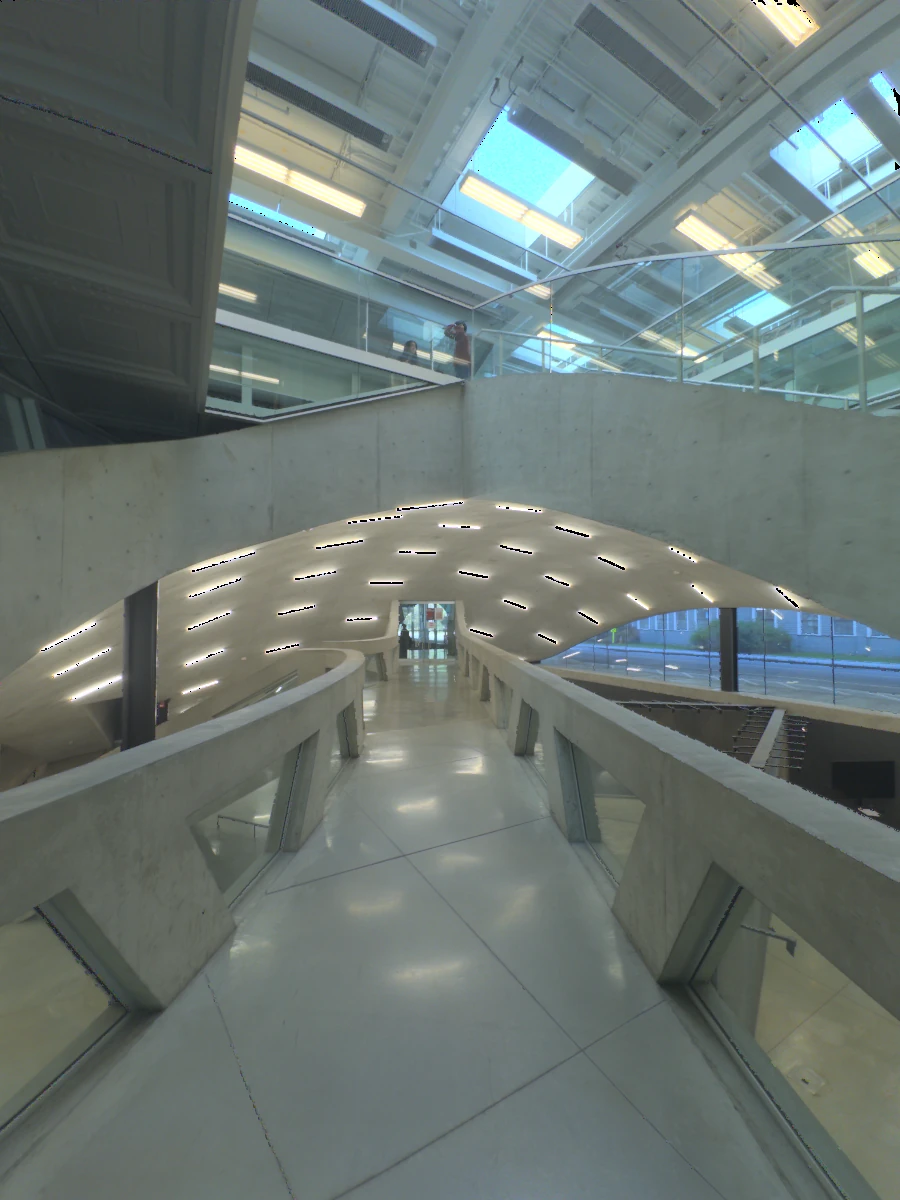
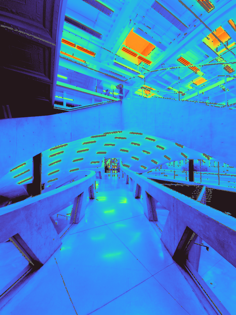
Milstein Dome

6 RAW exposures · Portrait · 3 reference points

Portrait iPhone HDR preview of the Milstein Dome interior with skylights, concrete ramps and glazed railings
Tone-mapped HDR preview. Numbers mark the saved reference points.
Luminance map and reference readings
Calibrated false-colour luminance map of Milstein Dome, showing the contrast between skylights, light fixtures and concrete surfaces
Rendered from the working HDR with its saved calibration factor, 0.9090.
Turbo colour scale from low luminance in purple to high luminance in red
101001,00010,000

cd/m² · Logarithmic scale

Saved calibration readings
PointMeter (cd/m²)Fit residual
11,266+15.7%
235.9−8.0%
355.3−6.0%

The saved merge excludes 3.8% of pixels from measurement. These appear grey in the luminance map.

The previews and luminance maps are rendered from the exported HDR data; they are not app screenshots. Both maps use the same 10–10,000 cd/m² range, with out-of-range values shown in the end colours. Residuals describe the saved fit to its own reference readings, not independent accuracy. The meter model was not recorded in these exports.

These Ultra Wide captures are for luminance studies. They are not complete 180° fisheye views and should not be used for the desktop glare workflow. Calibration does not replace validation of the camera, lens and measurement setup.

08 / FIELD CHECKLIST

Field measurement checklist

  • Record the design question and the metric that answers it, the camera position, eye height, gaze direction, date, time and sky conditions.
  • Use a tripod, fixed settings and overlapping exposures. Glare, the 40° band and Ev need a complete, characterized 180° fisheye view at eye height.
  • With the sun in view, add a characterized ND filter. For A/B comparisons, do not move the camera between captures.
  • Confirm useful shadows in a long exposure and unclipped important sources in a short one.
  • Measure and label several luminance targets in cd/m²; keep one for an independent check.
  • Record vertical Ev in lux at the lens before and after capture. Repeat if the scene changes.
  • For daylight models or task lighting, record a separate upward-facing workplane illuminance grid.
  • Check for motion and flare. Keep the originals and a measurement log with instrument details.
  • After processing, check calibration residuals and independent measurements before reporting results.
Download a field measurement log (CSV) ↓

09 / REFERENCES

References & further reading

This guide translates established HDR measurement methods into a student workflow. The papers provide the experimental methods, limitations and validation detail. Recommendations are starting points to validate with your own equipment.

  1. Mehlika N. Inanici (2006). Evaluation of high dynamic range photography as a luminance data acquisition system. Lighting Research & Technology, 38(2). Foundations: camera response, photometric calibration and lens effects.
  2. J. Alstan Jakubiec, Kevin Van Den Wymelenberg, Mehlika Inanici & Alen Mahic (2016). Accurate Measurement of Daylit Interior Scenes Using High Dynamic Range Photography. CIE Lighting Quality & Energy Efficiency, Melbourne. Aperture, vignetting, scene variability and luminous overflow.
  3. J. Alstan Jakubiec, Mehlika Inanici, Kevin Van Den Wymelenberg & Alen Mahic (2016). Improving the Accuracy of Measurements in Daylit Interior Scenes Using High Dynamic Range Photography. PLEA, Los Angeles. Bright sources, extended capture range and implications for visual comfort.
  4. Clotilde Pierson, Coralie Cauwerts, Magali Bodart & Jan Wienold (2021; first published online 2020). Tutorial: Luminance Maps for Daylighting Studies from High Dynamic Range Photography. LEUKOS, 17(2), 140–169. Open-access repository. A detailed calibration procedure and validation framework.
  5. Mehlika Inanici (2009). Applications of Image Based Rendering in Lighting Simulation: Development and Evaluation of Image Based Sky Models. IBPSA Building Simulation, Glasgow. Using measured HDR skies as simulation input.
  6. Jan Wienold & Jens Christoffersen (2006). Evaluation methods and development of a new glare prediction model for daylight environments with the use of CCD cameras. Energy and Buildings, 38(7), 743–757. DGP; evalglare implements it with UGR and source detection.
  7. David L. Loe, Kevin P. Mansfield & Edward Rowlands (1994). Appearance of lit environment and its relevance in lighting design: experimental study. Lighting Research & Technology, 26(3), 119–133. The 40° horizontal band and the ~30 cd/m² threshold.
  8. Illuminating Engineering Society (2011). The Lighting Handbook, 10th edition. Recommended luminance ratios between task, surround and periphery.
  9. Siobhan Rockcastle & Marilyne Andersen (2014). Measuring the dynamics of contrast & daylight variability in architecture: a proof-of-concept methodology. Building and Environment, 81, 320–333. Spatial contrast and its variation over time.
  10. EN 17037:2018. Daylight in buildings. Glare protection levels by DGP exceeded for no more than 5% of the occupied time.
  11. CIE S 026:2018, System for metrology of optical radiation for ipRGC-influenced responses to light; Timothy M. Brown et al. (2022), Recommendations for daytime, evening, and nighttime indoor light exposure, PLOS Biology, 20(3), e3001571. Melanopic EDI, M-DER and the 250 lx daytime recommendation.

About the developer. LumiSnap is created by Timur Dogan, Associate Professor of Architecture at Cornell University and director of the Environmental Systems Lab. His work connects daylighting, building performance simulation and architectural design.

Example photographs and measurement notes come from the supplied LumiSnap course capture series. All explanatory diagrams were drawn for this guide; values in the section 07 diagrams marked “example” explain each metric and are not measurements. Download the SVGs to edit shapes, labels and annotations in Illustrator or Inkscape; the example photograph inside the annotated diagram remains a raster image.

Download all thirteen editable diagrams (ZIP) ↓

LUMISNAP APPLICATIONS

Download LumiSnap

Get LumiSnap